Jablotron SmartHub Home Assistant link
- May 4, 2021
PLEASE NOTE: This concerns the (older IFTTT model) SmartHub from before 2024.
Jablotron SmartHub Home Assistant link
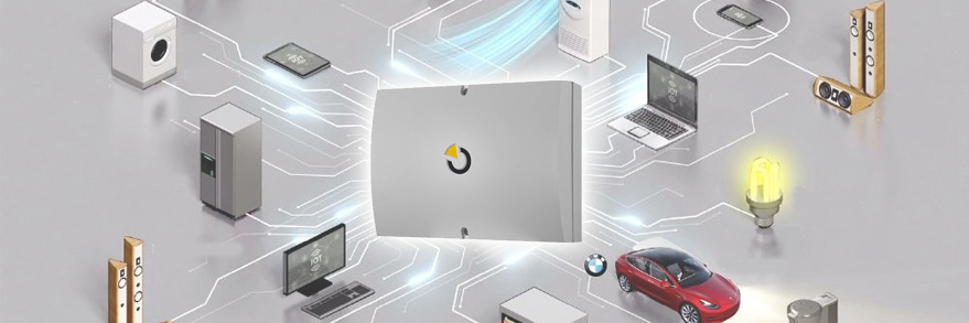
The SmartHub is an extra module to use the outputs of your Jablotron control panel as inputs for Home Assistant, but also for IFTTT. Now you can give all existing sensors of your Jablotron alarm an extra function, for example controlling lamps etc. The SmartHub can be ordered via the link and here you will also find (under downloads) the manuals for linking with IFTTT (simplest option) and Home Assistant. I will elaborate on the latter in this blog. I start with connecting and setting up the SmartHub and the control panel. Then the settings in Home Assistant including a number of possible applications for the outputs. I assume that Home Assistant is already present, the installation of this is a blog in itself but is well described here. If you find this too complicated, you can also use the SmartHub with IFTTT, setting up the SmartHub for IFTTT is described in this manual.
Connecting the SmartHub
Connecting the SmartHub to your exchange is fairly easy, provided you have the right materials at hand. The only thing that is not included is a network cable for connection to your home network and a network cable for connection to the central unit. It is best to use CAT6 for this. The SmartHub cannot be connected to your home network via the WIFI! Since the control panel is usually also wired to the network and the hub must be connected to the control panel, this is usually not a problem.
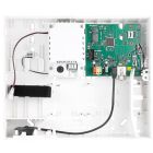
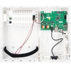
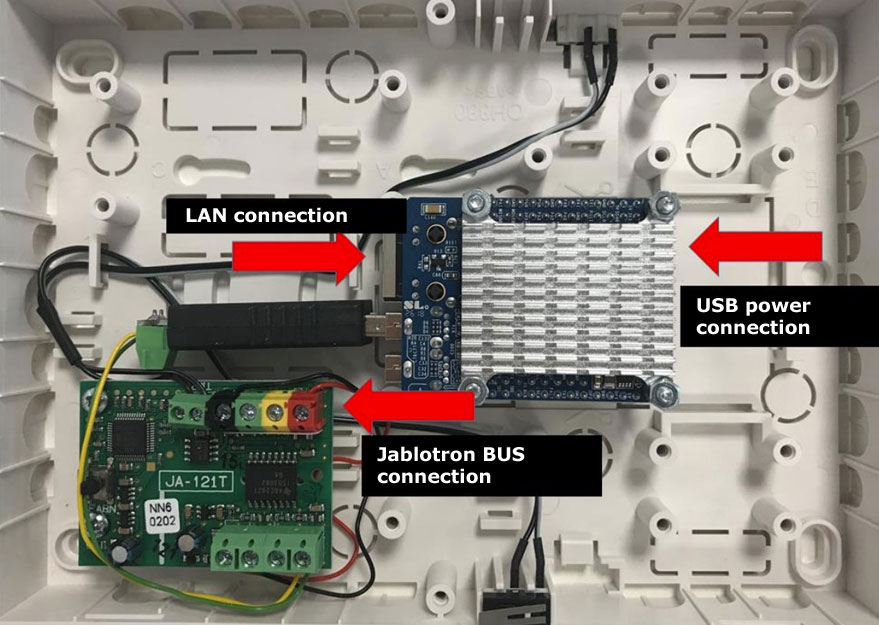
Below are the steps to connect the HUB (see also the image below):
- Click / cut one of the squares from the back of the HUB so that you can put the cables (power, network and towards the control panel) through;
- Connect the power supply to the control panel, leave the plug out of the socket for a while until you are completely finished with the connection and the HUB is hanging on the wall;
- Prepare the network cable for the connection between the HUB and the control panel by stripping a piece on both sides and also stripping four strands / cables at each end. Half a cm is enough for the small cables. Use a piece of CAT6 network cable for this, it has wires with a solid core which works a lot easier;
- Connect this to the bus in the HUB and take a picture that clearly shows which color wire you have connected to which color connection in the HUB.
- Then connect the network cable to the LAN connection in the HUB and the other end to your switch / home network.
- Screw the HUB to the wall and close it.
- Put your control panel in service mode and disconnect all power (including the battery).
- Connect the other end of the CAT6 cable to a bus connection in the control panel, making sure to connect the wires to the same color on the bus as they are connected to in the HUB.
- Power can be returned to the central unit and the HUB can also be plugged into the socket.
Bron: JA-SmartHub manual
Add SmartHub in the control panel and set PG outputs
Add SmartHub to the control panel
You do this by opening the F-Link software, activating service mode and then clicking on enroll on a free line (zone) under the devices tab. The HUB should then be found automatically. After that, in the Internal Settings column, click Enter and make sure the settings are as follows:
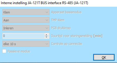
Then you can save the changes and we will set a number of PG outputs that we will need later in the SmartHub.
Configure PG outputs
In the F-Link software, a PG output must be linked to every detector or action that you want to use in Home Assistant. Please note, depending on the type of control panel, there is a limit to the number of PG outputs of 16, 32 or 128. On the initial setup tab, first set the number of PG outputs to the maximum available for the control panel or to the number of PGs. outputs that you need (if you have already mapped this), then click save. You can then click on the button on the Devices tab in the Activates PG column and link the device to a PG output by ticking one.
Screen shot BEFORE a PG output has been selected:

After:

It is useful to make a print screen of the Devices overview (like the second screenshot) if all devices you want to use in Home Assistant are linked to a PG output > you can use this to set up the PG output tab.
Then go to the PG output tab. A number of settings have to be adjusted here.
Screen shot PG output tab before settings are changed:

- 1. With the overview of the previous tab, you can change the Name PG to the names of the devices you have linked. The position of the PG output is the number that you ticked in the devices tab.
- 2. In the Functioncolumn you can choose a number of options:
- For a motion detector, doorbell, etc., choose Impulse, so you must enter a time in the Time column. One second should be enough, but we entered 00:00:03 here (3 seconds) so that the pulse is certainly long enough.
- With a magnetic contact or smoke detector, you choose Switch on / off and you do not have to choose other options.
- 3. You can also link a PG output to an action here, for example switching on fully or partially, switching off the alarm or triggering the alarm. This can be used in Home Assistant, for example, to turn down the heating or to turn the lights on or off. For this, the heating and / or the lamps must of course also be created in Home Assistant. How to link a PG to an event:
- Select a free PG output, it must not yet be used for a motion detector or the like.
- In the Activation column, click the Activation button.
- Then choose at Reaction the action you want to pass on to Home Assistant. If you want to use the activation and deactivation of the alarm in Home Assistant, you need three PG outputs. One for full arming, one for partial arming and one for disarming.
- Then choose Impulse again in the Function column and 00:00:03 again at time.
Screenshot PG output after application settings

After these settings have been saved, we can continue setting up the SmartHub. This receives the notifications from the PG outputs that you have just created and converts them into messages that can be used as inputs by Home Assistant. The control panel can also be taken out of service Mode because nothing has to be set here anymore.
Set up the SmartHub
To set up the SmartHub, go in a browser (locally) to "http://ja-hub.local:1880/". Here you log in with username admin and with the password Jablotron (with capital letter). The password cannot be changed and must be entered again after 7 days. You will then see the screen below.
This guide explains the steps in detail, I will show below the specific settings required for Home Assistant.
Once you are logged in, you will see the screen below.
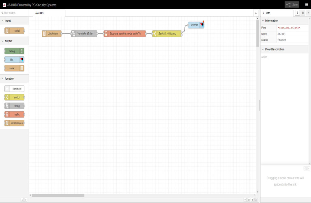
- 1. Click on the three dashes at the top right of the screen and then on Manage Palette. On the right-hand side, click on Palette if it is not already selected and at filter nodes you can type home or assistant. Then you should get to node-red-contrib-home-assistant-llat (see screenshot below). Here you click on install. Then go back to the start screen and click Save at the top. Then unplug the SmartHub for a few seconds to restart it.

- 2. When the SmartHub has restarted, you can click on the block with event1 and press delete (on your keyboard or by opening the block and then on the delete button).
- 3.You should then see a number of blocks related to Home Assistant on the left side of your screen. Drag the call service block to the place where the event1 block used to be.
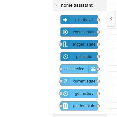
- 4. Double click on the call service block and select Add new server under Server. Click on the pencil behind this field. You will then arrive at the following screen:
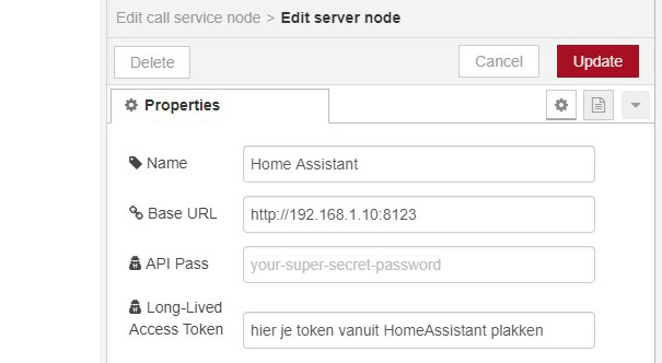
Name speaks for itself. At Base URL, the url of your Home Assistant must be entered. In the above URL you should only change the IP address to the IP address of your Home Assistant. You have to create the Access Token in HomeAsssistant by clicking on your username at the bottom left and then you will find Long-Lived Access Tokens at the bottom of your profile. Click on create, give a name to the token (eg alarm) and then copy the complete code. Paste this in the Long-Lived Access Token field in the screenshot above. Then click update.
- 5. Then double click on the Message > Exit block. Here we are going to set which messages should be converted from the exchange to a signal to Home Assistant (via the call service block). You must create one or two rules for each PG output that you have set in the control panel. You need two lines for all detectors (door/movement/smoke, etc.). For PG outputs for events (alarm on / alarm off etc.) you create one rule. In the screen below you can see what this looks like for the PG outputs that we just set up in the control panel.
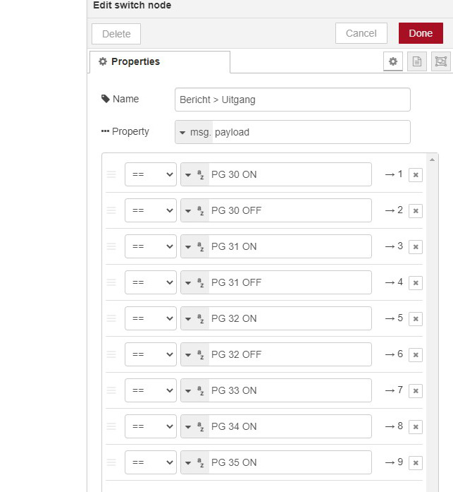
You must copy this exactly with the exception of the numbers, these must be equal to the numbers of the PG outputs in your own exchange (Position column). PG 30 is therefore the motion sensor, 31 is a magnetic contact, etc. PG 33, 34 and 35 are in this example events, e.g. alarm armed, disarmed or partial arming. In contrast to the sensors, these do not have a PG XX OFF rule.
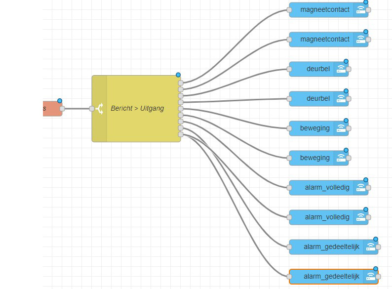
If you then click on Done at the top left, you will see that your Message block has received more dots on the right. For each line you get such a 'contact'. We are going to connect the call service blocks to this.
- 6. The call service block receives a signal when the SmartHub sees PG XX ON passing by, in the block we indicate what should be sent to Home Assistant next. It is therefore important that you also link the call service blocks to the top two lines (PG 30 ON and PG 30 OFF), which in this case pass on the status of the magnetic contact to Home Assistant. The call service block also has such a circle on both sides, drag a line from that circle to the top circle of the message block. It will soon look like this:
The easiest way is to create the first block and then copy it. To do this, we double click on the block and set it up as follows, with the left screen at the top message output (PG 30 ON) and the right screen at the second output (PG 30 OFF).
You do not have to open the message block every time, if you hold the mouse over an exit you will also see which 'message' is linked to it.
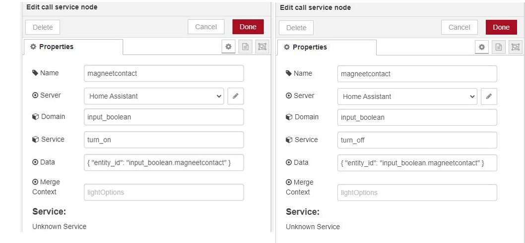
- At Name you enter a recognizable name, instead of magnetic contact it is better to use the front door / bedroom window etc if you have many sensors in your alarm.
- At Server you choose the server you created in step 4 (Home Assistant if all is well).
- At Domain you always choose input_boolean.
- At Service, choose turn_on at PG XX ON and turn_off at PG XX OFF.
- At Data, enter the following: { "entity_id": "input_boolean.magnetcontact" }
where input_boolean.magnetcontact is the name you give the input in Home Assistant. It is also useful here to give a recognizable name, but please note that this must match exactly when setting up the Home Assistant.
- Use only lowercase letters and no spaces with all these fields!
- Then you can click on done. You can now make the second block (right screen shot) by clicking on the first call service block, which is now probably called a magnetic contact or front door, and copying (ctrl + c) and pasting (ctrl + v) it. So attach this to the second message block output and change turn_on to turn_off (see the above two screenshots).
- You also do this for the other PG outputs that you have created in the control panel.
- The status/event outputs work slightly differently. In this example, PG 33 ON is associated with the alarm full set event (third message output from the bottom), PG 34 ON is part set (second message output from the bottom) and PG 35 ON is alarm disarm (bottom message output). In the control panel there is PG output 33 via the button activation, then, at reaction, selected for full arming etc etc.
Below the blocks of alarm_completely Arm (linked to PG 33 ON) and alarm_completely Disarm. The latter (right screen shot) is associated with PG 35 ON because it is associated with the turn off / disarm event in the control panel. For alarm partial arming you will also get two blocks again, but you can also choose the block with which you pass the disarming at the message block output PG 35 ON, since the control panel does not have a separate event for disabling a full arming or a partial arming. You can also see this in the screenshot with the overview of the blocks, the turn_off block of alarm_fully and the turn_off block of alarm_partly are linked to the last message block output.

When all blocks have been created, click on save at the top right. It is useful to keep the screen open since you now have to create the inputs in Home Assistant.
Settings Home Assistant
In Home Assistant, the inputs must be created so that they can be used as input for an automation or to display the status on a dashboard. Here I will discuss the specific device to bring in the inputs from the alarm, but I do assume some knowledge of Home Assistant. I make changes to configuration files or folders myself in Visual Studio Code (to be installed via Supervisor -> Add-on Store), but they can also be made in the File editor that can also be installed there. It is always useful to make a snapshot or other backup of your Home Assistant server before making any changes to the configuration.
- 1. If you don't already have it, add the line input_boolean: !include input_booleans.yaml in your configuration.yaml file.
- 2. In the same directory as your configuration.yaml file, create a new file with that name (input_booleans.yaml).
- 3. In this file you create the inputs as follows:
magnetcontact:
name: Magnetcontact frontdoor
initial: off
icon: mdi:door
doorbell:
name: Doorbell frontdoor
initial: off
icon: mdi:doorbell
movement:
name: Movement entrance
initial: off
icon: mdi:motion-sensor
alarm_fully:
name: Alarm fully armed
initial: off
icon: mdi:alarm-panel-outline
alarm_partial:
name: Alarm partially armed
initial: off
icon: mdi:alarm-panel-outline
It is important that the part before the “:” exactly matches the yellow shaded part that you entered in the call service blocks in the Data field { "entity_id": "input_boolean.magneetcontact" }
After name: you can then choose a name for the sensor, here you can use capital letters and spaces. At initial it is generally useful to choose off, this is the status that the input gets after a restart of Home Assistant. Optionally you can choose an icon for the input. This works in the same way as in other places in Home Assistant.
- 4. After you have set the above, go to configuration in the left menu and to server controls. Click on check configuration and if no problems are found then a bit lower under YAML configuration reloading on INPUT BOOLEANS. You should already see the inputs in Home Assistant and they can now be used for automation.
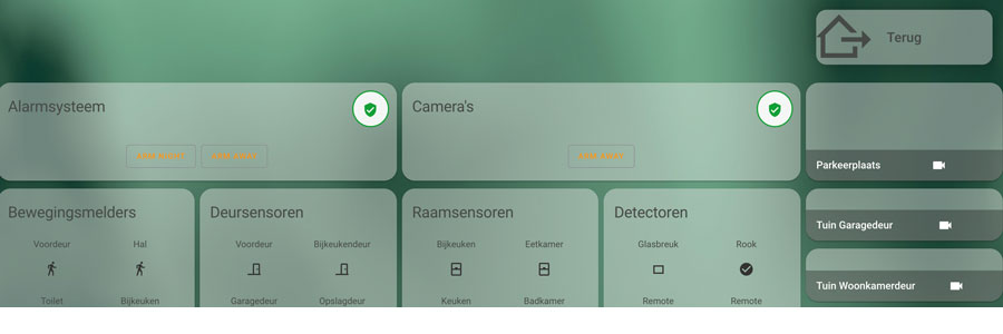
- 5. If you want to display them on a dashboard, e.g. like the screenshot below on a glance card, it is more convenient to make a template sensor for each input. If you only want to use the inputs as a basis for an automation, e.g. to switch lighting, you can skip this step and start automating immediately.

- If you don't already have it, add the line binary_sensor: !include binsensors.yaml in your configuration.yaml file. The file name can also be different eg binary_sensors.yaml.
- In the same directory as your configuration.yaml file, create a new file with that name (binsensors.yaml). In this file you create a sensor for each input.
Below is the setup for the above five inputs, a sensor is not very useful for a doorbell because you don't put it on a dashboard:
- platform: template
sensors:
magnetcontact:
friendly_name: "Magnetcontact frontdoor"
device_class: door
value_template: "{ { is_state('input_boolean.magnetcontact', 'on') } }"
movement:
friendly_name: "Movement entrance"
device_class: motion
value_template: "{ { is_state('input_boolean. movement', 'on') } }"
delay_off: 00:00:40
alarm_fully:
friendly_name: "Alarm fully armed"
value_template: "{ { is_state('input_boolean.alarm_fully', 'on') } }"
icon_template: mdi:alarm-panel-outline
alarm_partial:
friendly_name: "Alarm partially armed"
value_template: "{ { is_state('input_boolean.alarm_partially', 'on') } }"
icon_template: mdi:alarm-panel-outline
The headers again become the names of the sensors, these may be the same as the name of the inputs as above, but this is not necessary. Friendly_name is the full name, here again capital letters and spaces may be used and the choice of name is free. Device class is useful to specify, then automatically a number of properties such as status and the icon. You can find more information about template sensors and the available device classes here. You can copy the value template from my examples, note that the shaded part must match the name of your input boolean!
{ { is_state('input_boolean.alarm_partial', 'on') } }
With motion detectors you can set a delay_off in the format hh:mm:ss so that they are still displayed as active on your dashboard for a while if movement is detected. Otherwise you happen to have to look at the moment of the movement on your dashboard, the duration is freely adjustable. There is no device class available for the status of the alarm, so you can work with icon_template there to link an icon to the sensor.
- 6. Just check your configuration via the menu and this time reload the template entities and then you can add the sensors to your dashboard and your alarm is integrated with Home Assistant! That way you can use sensors or alarm statuses as input for your automations. Some examples are:
- Use motion alert to turn on or turn off lights when there's no movement for a specified period of time;
- Automatically lower the heating when the alarm is armed (full);
- Using the Jablotron Jablotron JA-159J button as a doorbell;
- Play a notification about your smart speakers when the garage door opens.
In addition, Home Assistant keeps a log so that you can also review the reports from your sensors. By linking the alarm, you can use all sensors already present in your house in Home Assistant for the purchase price of the HUB.
Small tip for setting the Trigger when you start working with automations. Use State as trigger type, choose the Entity e.g. input_boolean.magnetcontact or binary_sensor.magnetic contact if you have also created one and then enter off at From and on at To.
Hopefully this will give a good impression of the possibilities and this blog will help to quickly set up the SmartHub and link it to Home Assistant.
.


