Jablotron JA-KNX Interface
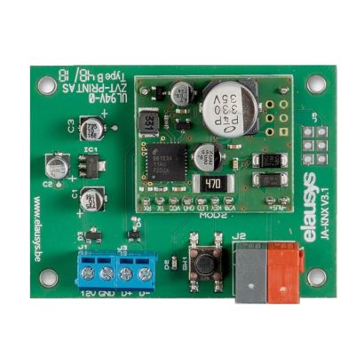
JA-KNX is a KNX gateway for the Jablotron 100 alarm systems.
It enables bidirectional communication using the RS485 communication module (JA-121T) from Jablotron.
There are 2 models: standard or DIN-Rail.
Jablotron JA-KNX Interface
The KNX interface module JA-KNX is a KNX gateway for the Jablotron 100 alarm systems. It enables bidirectional communication with the alarm system using the RS485 communication module (JA-121T) from Jablotron.
It allows integrators to take advantage of a fully integrated alarm system including KNX scenarios, automatic lighting using the motion detectors, arming or monitoring the system using a KNX visualization.
This interface is intended to be used with a JABLOTRON 100 series alarm system. The system must be equipped with a JA121T module for RS485 communication.
Standard model: this model is supplied from the bus and mounted in alarm panel only.
DIN-Rail model: this model needs the 12V power supply from alarm panel (or other) and can be mounted in the alarm panel as an empty PCB or on a DIN rail using the optional enclosure.
- KNX Interface for Jablotron 100 alarm systems
- Real time status of up to 96 zones
- Up to 32 additional bidirectional input/output (PG)
- Control up to 4 areas (arm/partial/disarm)
- 9 status per area (intrusion, entry, exit, fire,…)
- Recall of KNX scenes for each status
- Built-in termination resistor for RS485
- Communication fault monitoring
- Optional DIN-Rail enclosure (JA-KNX V3 only)
CONNECTION
The RS485 bus must be interconnected between the JA121T and the JA-KNX interface using the blue screw terminals on both modules. The termination resistor is already integrated on the KNX interface module, therefore no additional component or wiring is required.
SOFTWARE
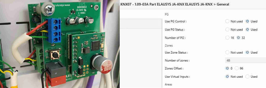
Configuration of 16 or 32 PG's are available and will be listed in the device group objects.
Each PG of the Jablotron alarm system can be controlled by a Group object and its status is retrieved on a separate group object.
|
GO |
NAME |
DESCRIPTION |
|
1 |
PGx |
PG Control from KNX |
|
2 |
PGx Status |
PG status |
Configuration of up to 96 zones are available and will be listed in the device group objects.
By default, zone status is configured for zone 1 to 96 of the alarm system. A general parameter allows to change for zone 97 to 192. Having then the possibility to use two gateways in the same installation to cover up to 192 zones of the alarm system.
Each ZONE has 1 Group Objects (GO) for the status to KNX.
|
GO |
NAME |
DESCRIPTION |
|
1 |
Zone x Status |
Zone status
|
Each area can be controlled by using the 3 group objects: Arm, arm partially or disarm. Several statuses are available and have a dedicated group object. Up to 4 areas are listed in the group objects.
A scene can be assigned to each status. This scene number will be recalled each time the zone status is active (ON).
Each area has 12 Group Objects (GO), 3 for control and 9 for the status to KNX.
|
GO |
NAME |
DESCRIPTION |
|
185 |
Area x – Arm |
Arm the Area |
|
186 |
Area x – Partial arm |
Partial arm the Area |
|
187 |
Area x – Disarm |
Disarm the Area |
|
188 |
Area x – State disarmed |
Area x status |
|
189 |
Area x – Entry delay |
Area x status |
|
190 |
Area x – Exit delay |
Area x status |
|
191 |
Area x – State armed |
Area x status |
|
192 |
Area x – State partial armed |
Area x status |
|
193 |
Area x – Fire alarm |
Area x status |
|
194 |
Area x – Siren ON |
Area x status |
|
195 |
Area x – Panic alarm |
Area x status |
|
196 |
Area x – Intrusion alarm |
Area x status |


